
On 10 July 2026, China took a significant step forward in the development of reusable launch vehicles, successfully recovering the first stage of the Chángzhēng 10B (“Long March 10B”) using a naval platform equipped with a net of ropes. The images released show a system that is completely different from those adopted so far by SpaceX in its two launch vehicles (the one currently in service and the one under development): the booster does not land on retractable legs, like the Falcon 9, nor is it gripped by two large rigid arms like the Super Heavy of Starship, but is intercepted by a flexible structure consisting of cables, attachment devices and damping systems installed on an offshore platform.
Analysis of Chinese patent databases now makes it possible to reconstruct much of the technical architecture of this system. Whilst it cannot be stated with certainty that all the patents identified were actually used on the Chángzhēng 10B, they describe solutions that are extremely consistent with what can be observed in the available footage and photographs, enabling us to understand the key design choices made.
A very simple system
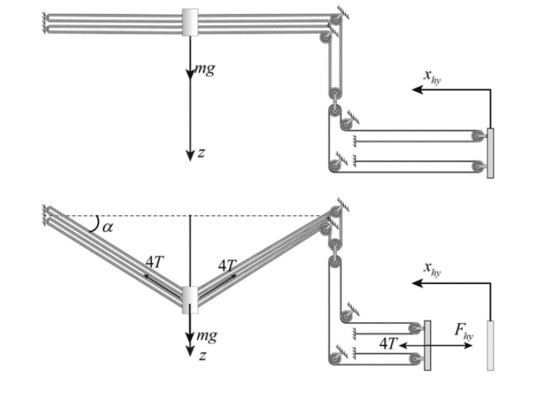
The operating principle is surprisingly different from that of other recovery systems currently in operation. During the final seconds of re-entry, the Chinese booster slows down using its own propulsion, but does not necessarily have to reach zero vertical velocity before contact. It is sufficient for it to pass through a capture aperture formed by metal cables, whilst maintaining a residual velocity compatible with the platform’s absorption capacity. From that moment on, the kinetic energy is not dissipated at a single point, but is progressively distributed along a series of mechanical components: hooks, arresting rods, cables, pulleys, dampers and a hydraulic circuit work together to transform a potentially destructive impact into a gradual deceleration.
Unlike a traditional powered landing, the booster is therefore not brought to a halt in a single instant, but through a chain of devices that progressively absorb the residual energy. The impact is distributed over time and across various elements of the structure, significantly reducing the load peaks transmitted to the rocket and the platform.
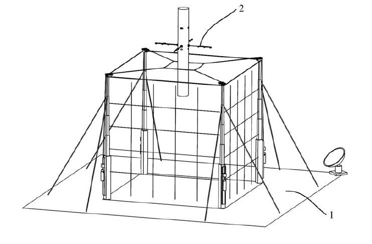
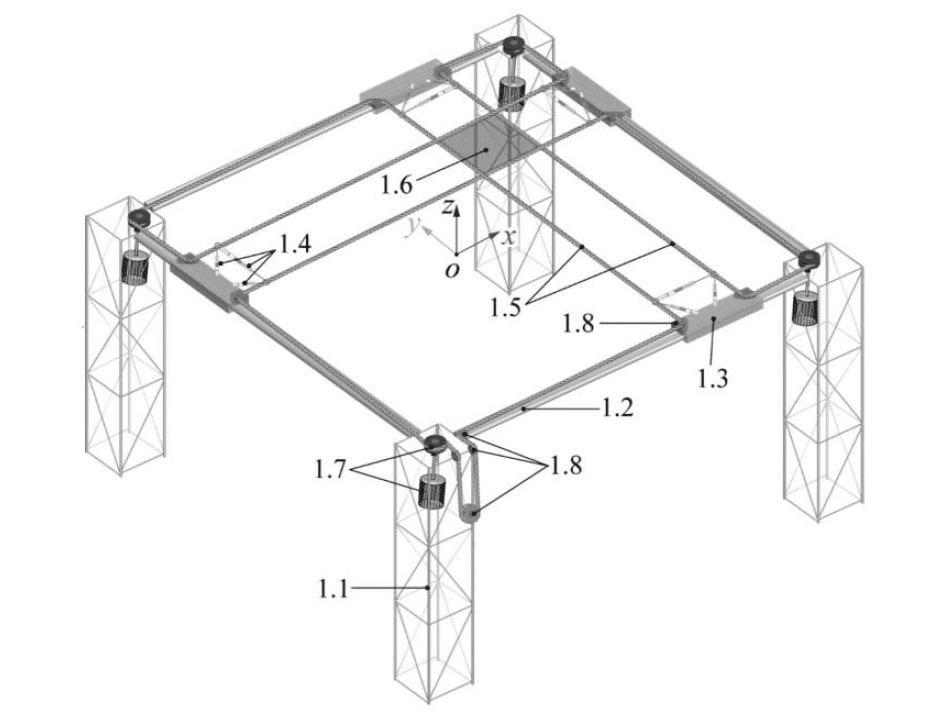
The recovery platform consists of a structure with four columns that enclose a central opening in which a network of metal cables is installed, forming the capture opening. This network is not a simple elastic net, but a system of high-strength metal cables connected to pulleys, deflection devices and damping systems.
At first glance, it may seem surprising that a space booster can be captured and supported by cables. In reality, the principle is not very different from that used in cranes, port lifting systems or large industrial installations: suitably sized steel cables can withstand very high loads, and the use of multiple cables allows the stresses to be distributed across different points of the structure.
The decisive factor, however, is not merely the weight of the booster, but above all the way in which it is brought to a halt. If a descending rocket were to be stopped instantly by four rigid cables, the force peaks would be enormous. In the patented systems, on the other hand, the cables work in conjunction with pulleys, moving parts and hydraulic damping devices that allow for a gradual deceleration. In this way, the booster’s residual kinetic energy is dissipated over time, reducing the maximum stresses on the cables, the hooks, the rocket structure and the platform.
Comparison with the competition
One of these Chinese patents describes a numerical model relating to a 25-tonne booster, with a residual velocity of 20 m/s and a deceleration distance of approximately 10 metres. This is a design example, not necessarily reflecting the actual weight of the launcher used in tests, but it is useful for understanding the order of magnitude of the problem.
For example, SpaceX’s Falcon 9 weighs around 550 tonnes at lift-off. After consuming almost all its propellant, the first stage, which returns for recovery, has a mass in the region of 25–30 tonnes. The Falcon 9 lands on its own legs.
In contrast, in the case of Starship, the masses are much greater: the entire system exceeds 5,000 tonnes at take-off and the Super Heavy booster, even when almost empty, remains in the region of several hundred tonnes. This is why SpaceX has adopted a capture system using the tower’s arms, rather than recovery via landing legs.
To give an intuitive comparison, 25 tonnes is roughly equivalent to the mass of a fully loaded shipping container; 40–50 tonnes is comparable to a large, fully loaded articulated lorry, a small rail vehicle, or one or two heavy containers.
Furthermore, the Faloria cable car in Cortina d’Ampezzo, which carries 50 people, weighs around 5 tonnes when empty and around 10 tonnes when fully loaded. The Ha Long Queen Cable Car in Vietnam, which carries 230 passengers, weighs 20 tonnes when empty and around 40 tonnes when fully loaded.
These are considerable masses, but entirely commonplace in industrial handling systems using cranes and steel cables.
Steel, cables and pulleys
For this reason, the real technical challenge lies in correctly sizing the cables and, above all, controlling deceleration so that the dynamic load is distributed gradually and does not result in an almost instantaneous impact. It is precisely this aspect that the patents emphasise most, describing pulley systems, hydraulic damping and tension control designed to ensure that the capture mechanism can cope with the enormous energies involved.
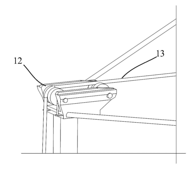
During capture, metal cables—particularly steel cables—are subjected to tensile stress, a condition under which they offer an excellent strength-to-weight ratio. Unlike a rigid structure, the net can deform, sag and progressively redistribute the loads, thereby increasing the time required to halt the booster and reducing the maximum force transmitted to the structure.
The net’s deformability also offers a further advantage: it increases tolerance to the inevitable residual trajectory errors. A rigid system requires the booster to reach the intended point with extreme precision; a flexible structure, on the other hand, can guide the vehicle towards the centre of the capture zone, compensating for minor lateral errors and reducing the demands placed on the guidance system.
Hitting the mark in one go
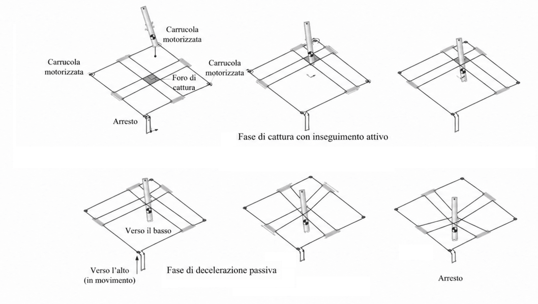
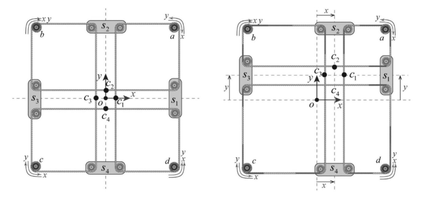
One of the most interesting aspects to emerge from the patent analysis concerns the fact that the net does not remain stationary whilst the booster is approaching. Several patents describe a platform in which the net and the capture hole can be moved in real time by motorised sliders running along linear guides.
Cameras and optical sensors continuously monitor the rocket during its descent and determine the position of the vehicle’s top and bottom, as well as the sides of the frame. The system then calculates the deviation between the predicted trajectory of the booster and the capture opening, controlling the motors so that the opening moves beneath the rocket.
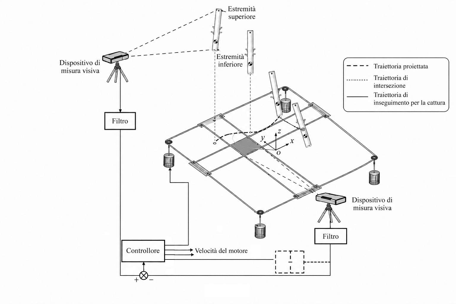
This solution allows small residual guidance errors to be corrected automatically without requiring continuous propulsive corrections from the booster. In practice, it is not only the rocket that seeks out the net, but also the net that moves to meet the rocket.
To achieve sufficiently precise tracking, it is necessary to continuously know the position and velocity of the booster. However, the problem is made particularly complex by the fact that the rocket, the cables and the platform itself constitute a highly non-linear system, whilst the measurements from the cameras are inevitably affected by noise, vibrations and small errors.
Calculating the impact
The behaviour of the moving net is not described in the Chinese patents solely from a mechanical point of view, but is modelled using mathematical models of the entire system of cables, pulleys and trolleys. The cables are modelled using an Arbitrary Lagrangian-Eulerian (ALE) approach, which is particularly well-suited to representing flexible elements that slide through pulleys and continuously change configuration. In this way, the model takes into account the slippage of the cable, its winding and unwinding on the motorised pulleys, the movement of the sliders along the guides, and the transverse vibrations generated during the movement of the net (patents CN114572429B and CN114802829A).
In particular, the cable-slider system is represented by a rigid-flexible multibody dynamic model, into which the geometric constraints determined by the guides, the pulleys and the configuration of the capture frame are incorporated. The corresponding differential-algebraic equations, described in the patents, are reduced to independent coordinates using the Jacobian of the constraints and integrated over time using the Backward Differentiation Formula (BDF); the resulting non-linear equations are solved iteratively using Newton’s method. The result is a model capable of predicting, at every instant, the position, velocity and acceleration of the various elements of the net.
The Unscented Kalman Filter (UKF) operates on this basis. Visual measurement devices detect the position of the upper and lower parts of the booster and of characteristic points on the capture frame, but these signals are inevitably affected by measurement noise and cable oscillations. The UKF therefore combines the available measurements with the system’s dynamic model to obtain, in real time, a more accurate estimate of the position and movement of the booster and the net. Through the Unscented Transform, the filter evolves a series of sigma points within the model that represent the system’s state, and progressively derives updated estimates and their associated uncertainties.
The position of the booster estimated in this way is compared with that of the centre of the capture hole. The resulting error feeds a PD controller with a saturation function, which determines the speed of the motorised pulleys. By appropriately winding or unwinding the various sections of the cable, these move the carriages along the guides and translate the capture hole in both horizontal directions, enabling it to actively track the trajectory of the booster. The saturation function also serves to prevent initial commands from being too abrupt, thereby limiting discontinuities and vibrations of the net during tracking.
Essentially, the net is not simply moved towards the rocket: its behaviour is modelled mathematically, visual measurements are filtered and compared with the dynamic model, and the result is converted into commands for the pulleys that keep the capture opening aligned with the trajectory of the booster.
“Combination!”
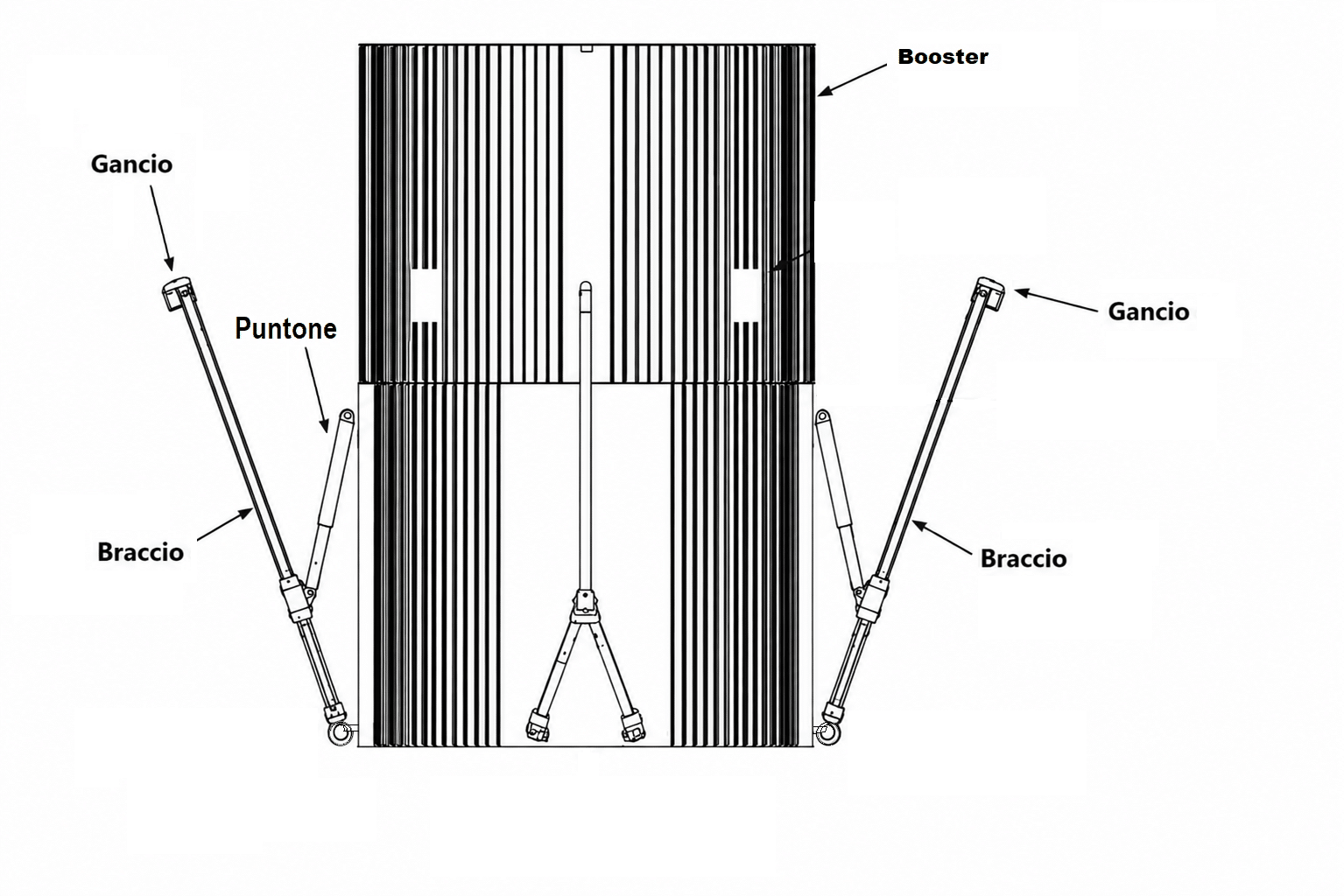
Once the booster passes through the capture aperture, the engagement devices fitted to the vehicle come into operation; these consist of a rod hinged to the rocket body which, during the final phase of re-entry, swings outwards to position itself almost perpendicular to the surface of the booster. At the end of the rod is a simple bayonet hook designed to catch the net’s rope (CN117128817).
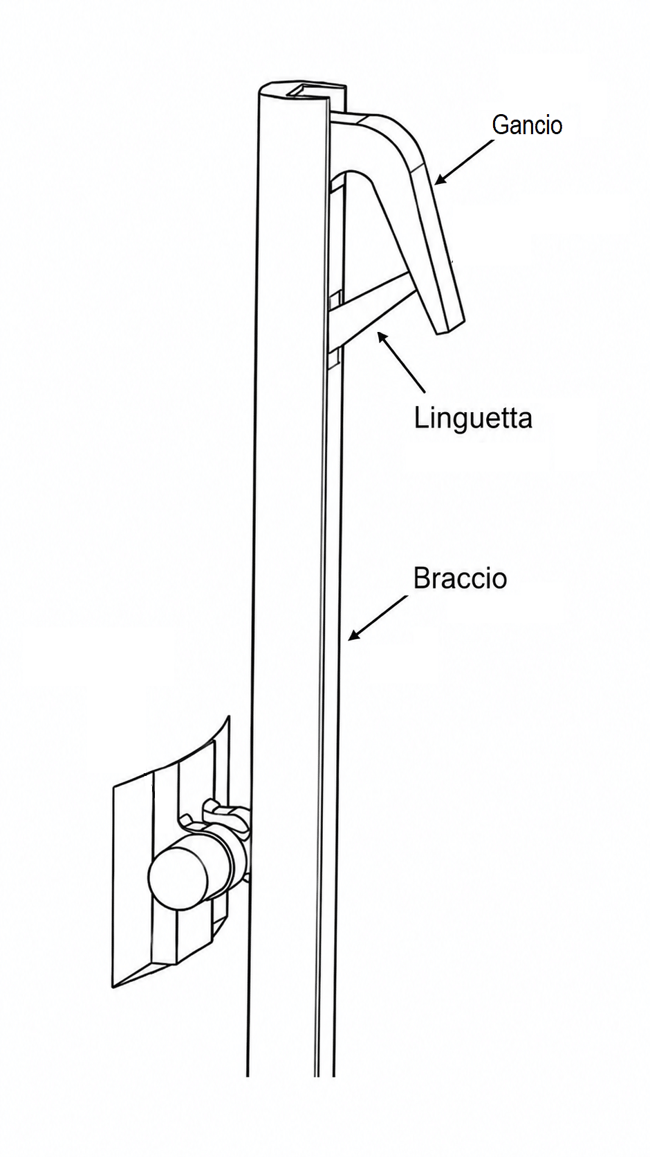
The mechanism is extremely simple yet effective. During descent, the rope enters the groove of the hook, pushing a spring-loaded hinged tab. Once the rope has passed through, the tab automatically returns to its initial position, preventing the rope from accidentally slipping out. In this way, the system allows the rope to enter in one direction but prevents it from travelling in the opposite direction during the subsequent braking phase.
The importance of the tab is particularly evident in the first few moments after engagement. The booster does not, in fact, come to a halt immediately: it continues to move, the net deforms, the ropes swing and the loads change direction rapidly. In the absence of a retention device, even a momentary slackening of the tension could allow the rope to slip out of the hook’s groove, compromising the entire recovery operation.
The most mechanically sensitive point of the entire system is the contact between the hook and the rope. Along the free length, the rope is subjected almost exclusively to tensile stress, whilst at the attachment point it is forced to bend around a curved surface, simultaneously experiencing tensile stress, local bending and contact pressures. If the radius of curvature were too small, the outer strands of the rope would deform excessively with each retrieval, leading to a rapid accumulation of fatigue damage. For this reason, a Chinese patent (CN117128817) specifies that the hook’s cylindrical bearing surface should have a diameter approximately three to five times that of the rope, thereby reducing local curvature, distributing pressures more effectively and increasing the rope’s service life. The same patent also stipulates that the hook must be easily replaceable, so that only the component most subject to wear can be replaced without needing to alter the entire coupling mechanism.
Impact damping
A telescopic damping strut is fitted between the coupling assembly and the body of the booster. As the rod extends, it controls the movement, preventing end-of-stroke impacts and unwanted oscillations; subsequently, when the cable is intercepted and the force increases rapidly, the strut absorbs part of the energy by progressively deforming (CN117128817).
Basically, the strut functions as a shock absorber fitted directly to the booster: rather than instantly transmitting the entire load to the rocket’s structure, it distributes the load over a controlled stroke, reducing the peak force and improving the stability of the entire system.
The energy is therefore dissipated across several stages.
A first portion is absorbed by the deformation of the net, a second by the relative movement of the cables on the pulleys, and a third by the telescopic strut fitted to the booster. The final phase of deceleration, however, is handled by the platform’s hydraulic system: once the booster remains suspended from the net, the residual descent pulls on the capture cables which, via movable pulleys, actuate a piston.
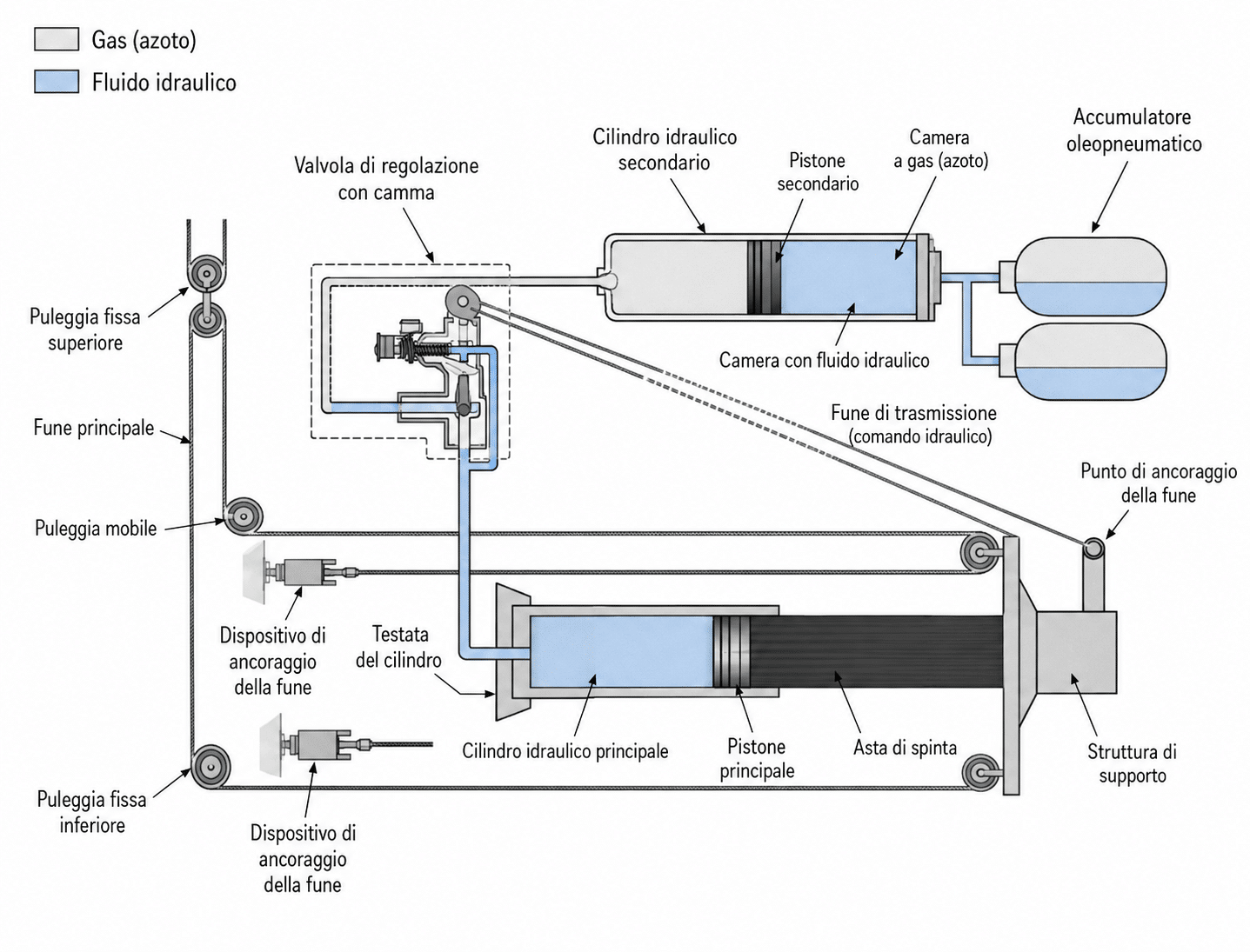
This compresses the oil contained in a hydraulic cylinder and pushes it towards a hydro-pneumatic accumulator, progressively converting the residual kinetic energy into hydraulic pressure, gas compression and heat, and preventing the load from being transferred instantaneously to the platform structure (CN114655474).
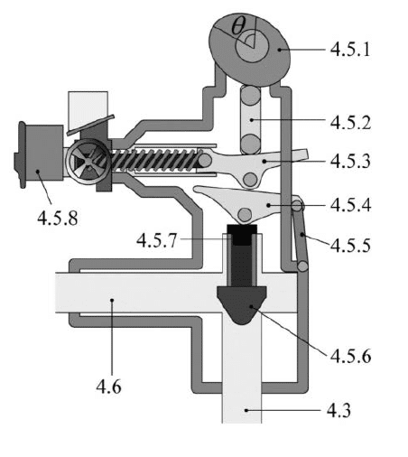
The most sophisticated aspect of this solution is that the braking force does not remain constant throughout the entire stroke. Excessively intense braking at the start would, in fact, place extremely high loads on the hooks and ropes, whilst insufficient braking would require a much longer stroke of the damping system. To resolve this problem, the movement of the piston actuates a cam that progressively adjusts the opening of the throttle valve in the hydraulic circuit. By varying the cross-sectional area available for the oil to pass through, the pressure inside the cylinder also changes automatically and, consequently, the braking force applied to the booster. The shape of the cam is therefore designed to achieve a precise deceleration curve, distributing energy absorption throughout the entire stroke of the device rather than concentrating it in a single impulse.
It is interesting to note that similar principles of progressive energy dissipation and damping control are also employed in cable systems, such as cable cars, where controlling the stresses on the cables and mechanical components is essential to avoid load peaks and ensure a controlled stop.
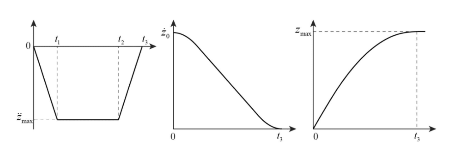
The simulations reported in the patent demonstrate precisely this behaviour. The case study considers a booster weighing approximately 25 tonnes with an initial vertical velocity of approximately 20 metres per second. The simulation curves demonstrate how velocity, hydraulic pressure, rope tension and deceleration evolve in a coordinated manner throughout the braking process, avoiding sudden load spikes (Figures 14 et seq. of CN114655474). The system is also equipped with a selector switch that allows the valve calibration to be adjusted, adapting the braking law to rockets of different masses.
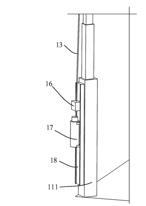
To prevent the booster from rebounding after coming to a halt, the platform also employs anti-rebound devices that prevent the cables from elastically releasing the stored energy. Without such devices, the net could behave like a large spring, causing the rocket to oscillate again. The combined use of dampers and anti-bounce systems, on the other hand, keeps the booster in a stable position immediately after capture (CN109911253).
Return to base
After capture, the booster must be secured and transported without compromising the stability of the offshore platform. A particularly recent patent describes a system in which a rotating annular structure automatically aligns a handling module with the rocket. The booster is gripped by cushioned clamps, gradually tilted from a vertical to a horizontal position and then pulled into a sealable cylindrical container (CN119197208).
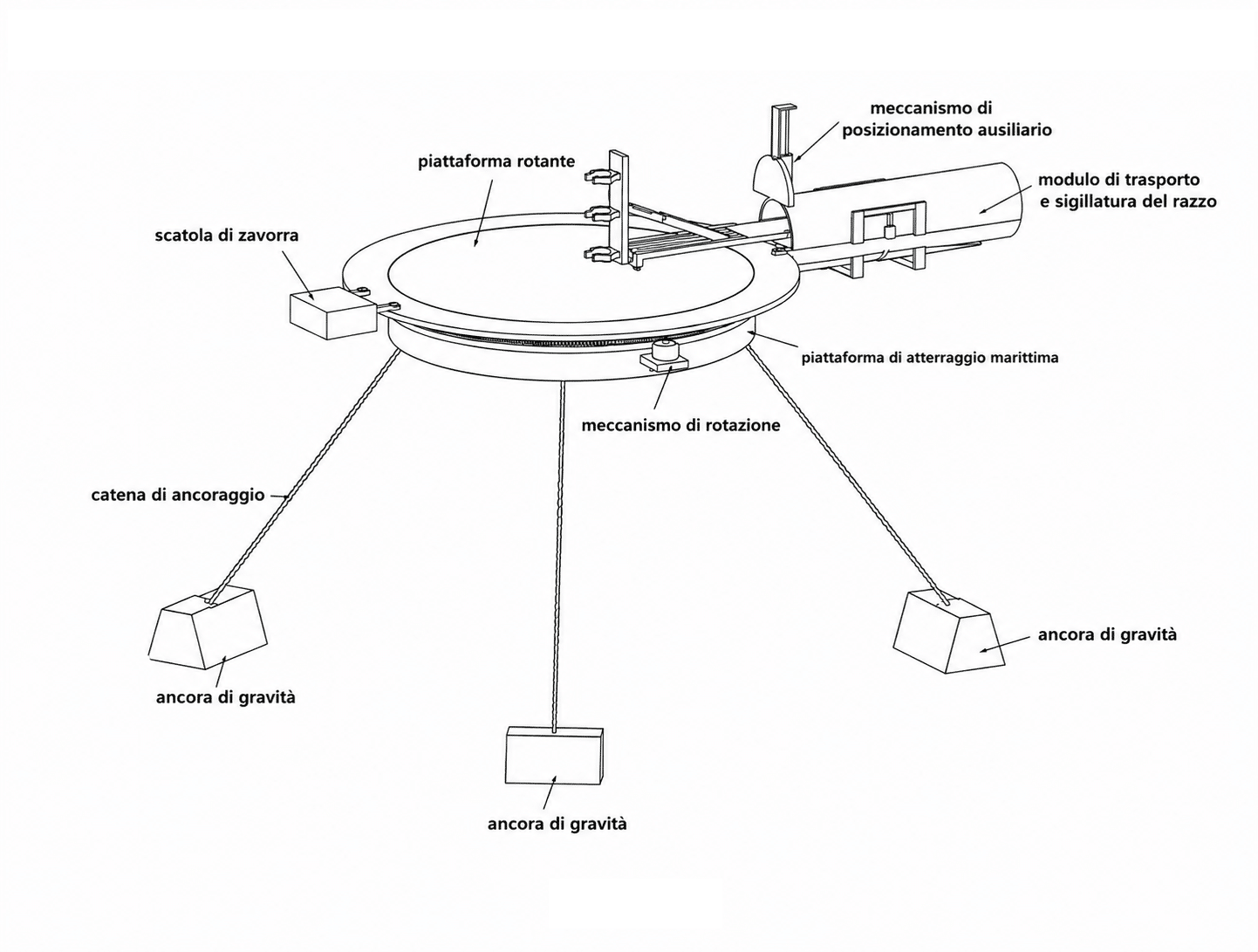
Once closed, the container can be separated from the platform and towed to port; retractable buoyancy chambers increase stability during maritime transport, reducing the risk of capsizing (CN119197208).
A technology not entirely accessible
Patent analysis also shows that China has not exclusively developed the solution based on a network of cables. In parallel, lightweight landing legs made of composite materials and their associated locking mechanisms have been designed. A reusable system keeps the legs folded against the rocket body during flight by means of two clamps with semi-circular seats, operated by a pneumatic or hydraulic actuator via a crank-and-connecting-rod mechanism. A latch prevents accidental opening, whilst return springs and a telescopic limit stop automatically return the mechanism to its initial position after each use (CN117704898).
These patents demonstrate that, at least in the early stages of development, architectures more closely resembling those adopted by the Falcon 9 were also explored, before the decision was made to adopt cable-net recovery.
One particularly unusual aspect concerns the patent protection strategy. Based on the public databases available in 2026, the main patents analysed appear to be limited to China alone, with no corresponding foreign extensions. This means that these specific inventions are protected only within Chinese territory and that, barring the existence of other rights, they could in principle be reproduced and used abroad without infringing these patents.
It is clear that certain crucial elements have been retained as confidential know-how, such as the cable pre-tensioning parameters, the actual damping curves, the materials and treatments of the hook, the coupling tolerances and, above all, the artificial intelligence systems that enable the system’s response to be trained on the basis of operational experience.
Furthermore, as the first successful rescue did not take place until 10 July 2026 and patent applications are published approximately 18 months after filing, it is likely that some of the most recent innovations, filed in 2025 or 2026, are not yet publicly available.
Furthermore, Chinese patents show that the capture system does not necessarily consist of a ‘net’ in the traditional sense of the term, but can take various forms based on taut and movable ropes. In one embodiment, a single continuous rope is passed through fixed pulleys, motorised pulleys and carriages to form a lattice structure with a central capture opening, the position of which can be adjusted horizontally by actuating the carriages and pulleys (CN114655474B, 15 February 2022; CN114572429B, 15 February 2022).
In another configuration, which appears to be the one adopted in the solution actually tested, the capture aperture is bounded by four cables, or more precisely by four interception sections arranged in parallel pairs at right angles to one another: the movement of the corresponding movable pulleys allows the central area to be shifted so as to align it with the trajectory of the booster (CN116718081A, 19 July 2023).
More generally, the various patented solutions therefore converge on the idea of a cable-based capture system, in which the geometry and position of the interception zone can be dynamically controlled to intercept the booster during the final phase of descent.
Conclusions
The value of these technologies extends far beyond the individual recovery system. The ability to reliably reuse the first stage has a direct impact on costs, launch frequency and, more generally, the industrial capacity for access to space. The Chinese patents demonstrate an attempt to develop a solution independent of the US model, by concurrently developing mechanics, sensor systems, control systems, energy dissipation and various complementary subsystems at different universities, research institutes and industrial entities. Whilst this does not in itself demonstrate full operational maturity, it does indicate a structured development path and the gradual build-up of proprietary know-how.
Space competition therefore increasingly centres on the availability of reusable, scalable technological infrastructure protected by industrial property rights. An effective recovery system can lead to greater launch frequency, reduced costs and the ability to rapidly deploy large civil, commercial and dual-use constellations.
A further critical element concerns the final re-entry phase, which is more complex than the launch, as the vehicle must correct for wind, turbulence, attitude errors and trajectory deviations in real time in order to reach the capture area with precision. Under these conditions, purely deterministic models are insufficient, and artificial intelligence systems trained on real-world data are crucial. Training also requires a great deal of real-world data and can take years to build a sufficiently comprehensive and reliable database. However, it is precisely these algorithms that tend not to be disclosed in patents, as they can be retained as confidential know-how and trade secrets.
For Europe, this is a particularly sensitive issue. Compared to the United States and China, we have a more limited base of computing infrastructure, data centres, operational data and real-world platforms on which to train and validate advanced control systems. Without a significant strengthening of these capabilities, it will be impossible to bridge the gap, not only in reusable launch vehicles, but in the aerospace sector in general.
The European Union has launched programmes to strengthen autonomous access to space and develop reusable technologies, through Horizon Europe, the SALTO project, the Themis demonstrator and new funding for innovative launch solutions. However, compared with the level of maturity achieved by the United States and the speed with which China is developing alternative architectures, Europe still appears to be lagging far behind in its ability to transform research and experimentation into competitive operational systems.
The issue, therefore, is not to determine whether the Chinese system is currently better than the American one, but to recognise that China is building its own technological architecture for the reusability of launch vehicles. It is in this area — the ability to innovate, industrialise and learn rapidly from real-world data — that an increasing part of the global space competition will be played out.
[Featured image: CC 4.0 China News Service, reworked using AI]
